
Yukon blog

How to Select the Right Gear Ratio for Your Vehicle
One of the most common questions we hear at Yukon Gear & Axle is: "What gear ratio should I run?" The answer depends on two things: What you're starting with What you're trying to achieve Choosing the right gear ratio isn't just about picking a number. It's about understanding your vehicle, how it's been modified, and how you plan to use it. Start with Your Vehicle's Current Setup Before recommending a gear ratio, we need a baseline. Important information includes: Year, make, and model Engine and transmission Axle type Current gear ratio Tire size Factory options This information helps us understand how your vehicle was originally designed to perform and gives us a starting point for making recommendations. What Has Been Modified? Modifications can dramatically affect gear ratio selection. Some common modifications include: Larger tires Engine swaps Transmission swaps Lift kits Heavy accessories like bumpers, armor, and camping gear For example, installing larger tires effectively changes your final drive ratio. While your speedometer may show the same speed, the engine now has to work harder to turn those larger tires. That's why many truck and Jeep owners choose to re-gear after moving to 35-inch, 37-inch, or larger tires. What Is Your Goal? There are many reasons to re-gear a vehicle. Some drivers want: Better acceleration Improved drivability More towing performance Better off-road capability Compensation for larger tires Improved fuel economy A specific performance setup for racing or competition Your goal determines the best gear ratio. For example, a drag racing vehicle, rock crawler, tow rig, and daily driver may all require completely different gear ratios to perform at their best. The Biggest Misconception About Re-gearing Many people assume that after installing larger tires, they simply need to return their engine RPM to factory levels. In reality, what most people want is to restore factory drivability. Modern vehicles are often geared very aggressively from the factory to help manufacturers meet fuel economy requirements. While this works well during testing, it doesn't always translate to the best real-world driving experience. Take a late-model Jeep as an example. Many factory-equipped Jeeps struggle to stay in their highest transmission gear on the highway. The transmission frequently downshifts because the engine isn't operating in its optimal power range. A properly selected gear ratio can allow the engine to run at a slightly higher RPM, where it produces better torque and operates more efficiently. The result? Better throttle response Improved drivability Less gear hunting Better towing performance In many cases, improved real-world fuel economy The goal isn't always lower RPM. The goal is to put the engine in a range where it performs best. Does a Lower Gear Ratio Make Your Axles Weaker? Another common myth is that lower gears are weaker and more likely to break. The truth is that this depends entirely on the axle and gear set design. For example, many popular Jeep gear ratios such as: 4.88 5.13 5.38 all use the same 8-tooth pinion design. Despite the different ratios, they share similar strength characteristics. So where did the myth come from? Decades ago, some extreme gear ratios used in specialty applications required very small pinion heads. In certain cases, the pinion gear became smaller than the shaft supporting it, creating a potential weak point. Examples include: Some older Toyota 5.71 ratios Certain Dana 6.17 and 7.17 ratios used in industrial and mining applications These specialized gear sets helped create the belief that all lower gear ratios are weaker. For most modern trucks, Jeeps, and off-road applications, that simply isn't the case. The Bottom Line Choosing the right gear ratio starts with understanding your vehicle and your goals. The best ratio for your build depends on factors such as: Tire size Engine performance Transmission gearing Vehicle weight Driving style Intended use There is no one-size-fits-all answer. That's why Yukon Gear & Axle works with customers every day to determine the best ratio for their specific application. Whether you're trying to restore performance after upgrading to larger tires, improve towing capability, or build the ultimate trail rig, selecting the proper gear ratio is one of the most important upgrades you can make. While online gear ratio calculators can provide a useful starting point, they don't account for factors like the ones discussed. That's why Yukon Gear & Axle recommends using a calculator as a guide and consulting with our technical experts to select the ratio that best fits your specific application.

Raising the Bar on Gear Installation: Inside the Yukon Gear & Axle Master Installer Program
At Yukon Gear & Axle, performance doesn’t stop at manufacturing high-quality drivetrain components. Real-world reliability depends just as much on the people installing them. That’s why the Yukon Gear & Axle Master Installer Class exists. This program is designed to raise the standard for differential and axle installation across the industry by providing installers with hands-on, real-world training using the same products they work with in the shop every day. We just wrapped up another successful Master Installer Class at LetzRoll Offroad, where 12 installers were officially certified after completing an intensive, hands-on training program focused on gear setup, axle assembly, and proper installation procedures. Built on Real World Installation Experience The Master Installer Class is a hands-on training environment built around real drivetrain setups and real shop scenarios. Installers work directly with ring and pinion specialists, differential assemblies, and axle components while learning the critical details that determine long-term performance, including: Gear pattern interpretation Backlash measurement and adjustment Bearing preload setup Proper installation procedures Diagnosing and preventing common setup issues This approach ensures installers don’t just understand the theory behind gear setup; they gain the confidence to execute it correctly in a professional shop environment. Why Yukon Invests in Installer Training Yukon Gear & Axle runs the Master Installer Program for one simple reason: better installation leads to better performance. Even the highest quality drivetrain components will underperform if they are not set up correctly. By investing in installer education, Yukon helps shops and technicians: Reduce installation errors and comebacks Improve long-term drivetrain reliability Increase efficiency and consistency in the shop Deliver better results for customers in towing, off-road, and performance applications With more than 140 certified Master Installers nationwide, the program has become one of the most respected training opportunities in the drivetrain industry. Many participants arrive with years of experience in gear setup and differential work, yet still leave with new techniques and valuable insights. Those who earn certification also gain access to a network of fellow Master Installers, creating a community of experts dedicated to raising the standard of drivetrain installation. This program is about more than certification. It is about elevating the automotive industry standard. Another Successful Class at LetzRoll Offroad Our most recent class at LetzRoll Offroad in Mesa, Arizona, brought together 12 installers who completed the certification program and demonstrated a strong understanding of proper differential setup and installation practices. The hands-on environment and experienced personnel at LetzRoll Offroad, alongside Yukon’s Tech Specialist Gus Pyeatt, provided the perfect setting for practical learning, allowing participants to apply techniques in real-time while working through installation challenges. Each certified installer leaves with the knowledge and confidence to perform precise, reliable setups that meet Yukon’s standards in both performance and durability. The Bottom Line The Yukon Gear & Axle Master Installer Class exists to raise the bar. By combining hands-on training, real-world applications, and product-specific education, the program ensures that installers are not only certified but also prepared to deliver high-quality results in the field. With 12 new certified installers from our latest class at LetzRoll Offroad, the program continues to grow its impact across the industry, one shop at a time. To learn more about the Master Installer Program, visit: https://www.yukongear.com/pages/master-installer
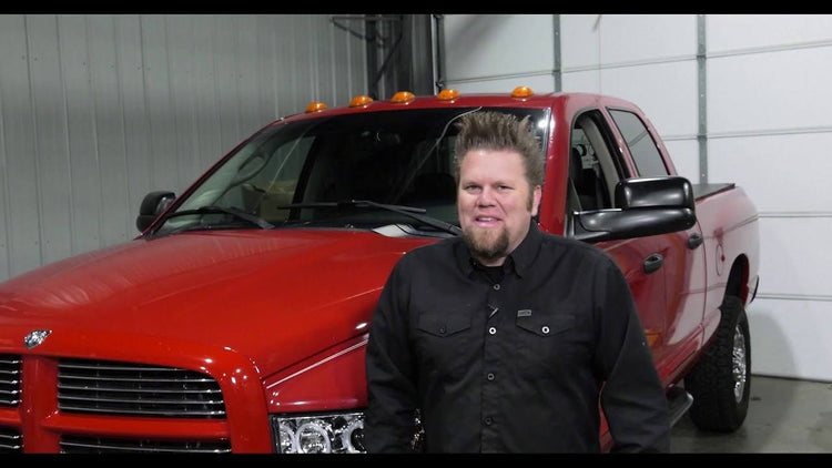
Ian "Big Tire" Johnson Spin Free Installation Video
Yukon Spin Free KitsFreewheeling in the Name of Fun and Efficiency Ian Johnson, the host of the TV show “Four Wheeler” on the MotorTrend Network, runs through all the details involved in installing a Spin Free Kit in the accompanying video. The four-wheel-drive systems on some Dodge and Jeep applications are engineered to turn the front axles and transfer case gears when the vehicles are in two-wheel drive mode. This is wasteful on two fronts. First is the wear and tear factor… which is complicated by the fact that these systems feature non-serviceable, failure-prone bearing assemblies. Then there’s the negative impact all the energy used turning the front drivetrain has on fuel economy. Yukon Spin Free Kits swoop in like a superhero to save the day by allowing the front drivetrain to freewheel. These kits replace the failure susceptible and expensive factory unit bearings with serviceable tapered bearings and races. The result is not only a design which is easier and more economical to maintain, but one that offers significant increases in fuel efficiency because mpg-stealing parasitic drag in the front drivetrain is reduced. Each Spin Free Kit includes new wheel hubs, spindles, high-strength Yukon 4340 chromoly outer axles, Yukon Hardcore premium locking hubs, high-quality bearings and seals, and all the hardware needed for installation. Kits are accompanied by a limited lifetime warranty against manufacturing defects for as long as you own the vehicle. Wasted effort is frustrating. Unnecessary wear and tear and costly repairs are frustrating. Sacrificing fuel efficiency is frustrating. Yukon Gear & Axle Spin Free Kits relieves the frustration and makes your rig less expensive to maintain while allowing it to run longer between fill-ups. It’s a win-win. About Ian Johnson A former high school auto shop teacher, Ian first hit the big time in 2005 as part of Spike TV’s Powerblock weekend programming. Ian co-hosted the popular “Extreme 4x4,” a hardcore how-to show that highlighted the building and modifying of off-road vehicles. After the Powerblock was cancelled in 2013, the show transitioned to Xtreme Off Road (XRO) on Paramount’s Power Nation programming block. Ian left XRO in 2017. He appeared briefly on “Big Tire Garage” before manning the helm of the highly successful “Four Wheeler” show when it debuted in 2019. Like his TV segments, this installation video goes full-tech as Ian highlights all the critical steps with enthusiasm and depth as only he can do. With his big hair and big fabrications skills, Ian is a well-known personality in the off-road industry. Check it out.

Unboxing: Gear & Install Kit Package
Part of our Yukon Gear & Axle product unboxing series.